The Polymetric Scintillator is indeed a high quality, precision instrument, but as with any complicated device, there will always be improvements that make things easier or more appropriate for one's individual style of work.
This document describes how to replace the fine angle adjustment bolt with a precision micrometer head. Not only does this give more precise, repeatable control of the cutting angle, but it overcomes a design problem inherent in the Scintillator.
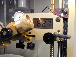
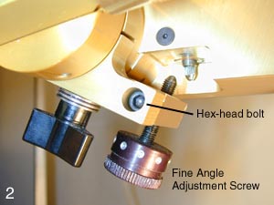
The figure at right shows the Scintillator head with digital angle readout and various controls. The fine angle adjustment bolt lies underneath the faceting head, as shown in figure 2 below.
I had several problems with the original adjustment screw. First of all, like the other fine adjustments on the Scintillator (height, cheat), there are no numbers for reference, making repeatable settings more difficult. I had corrected this by numbering the dots on a piece of white cloth tape applied to the various knobs.
The other problems are more difficult to address. The fine angle adjustment is a steel screw threaded through an aluminum block, with no hardened insert or helicoil. In situations requiring frequent adjustment or stress (for example working against the hard stop), such an arrangement is doomed to fail. With time and applied forces, the steel screw begins to "machine" the aluminum block, resulting in a looser and looser fit.
After only a dozen stones or so, my fine angle adjustment was very loose, so loose in fact, that brushing the knob with a shirtsleeve, or even repeatedly tapping the screw tip against the hard stop would change the angle setting significantly. Needless to say, this makes things difficult.
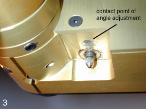
I was also concerned about the steel screw tip impacting the underside of the faceting head - the "hard stop." This part of the machine is also aluminum, albeit somewhat hardened by anodization. Nevertheless, the underside of my Scintillator was showing wear and tear after only a few months (see figure 3 at right).
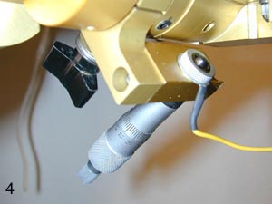
I found a very straightforward solution to these difficulties: replacing the adjustment screw with a micrometer head. The aluminum block in which the angle adjustment screw is mounted comes off readily by removing one hex-head bolt (figure 2). At a tradeshow, I purchased a surplus micrometer head for about $10. This head has 15 mm of travel and a precision of about 5 microns. It mounts securely in a 1 cm diameter hole using the supplied nut. Simply drill out the (worn) tapped hole to 1.0 cm diameter and mount the micrometer head and you are done (figure 4 at right).
There are of course, some additional details - for instance adding the wiring for a depth of cut indicator.
The tip of the micrometer head must be rounded. You may be able to find one like this, but mine had a (hard!) flat head, which was formed to a rounded shape on a grindstone.
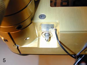
I was also worried about the aluminum hard stop, which would probably suffer more from the ultrahard steel of the micrometer head. I therefore glued a small steel plate to the underside of the faceting head (figure 5 at left - the photo shows a trial with 5 minute epoxy. It now looks much neater).
This plate, along with a clip under the micrometer head (figure 4) forms part of the circuit for a B-W type depth-of-cut indicator.
While modifying the adjustment screw, I took the opportunity to try a B-W type depth-of-cut indicator. This device takes advantage of the internal capacitance of analog ohm-meters to average out the mesaured resistance of a rapidly opening and closing circuit (minor variations in the flatness of the lap cause partial contact when you first hit the hard stop).
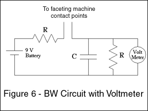
Unfortunately, my analog ohm-meter was too responsive - it fluttered uncontrollably at the critical contact point. Instead, I use a small battery-powered circuit and a voltmeter. Figure 6 shows the necessary components. Select the resistors and capacitor so that the RC product is approximately 1, giving a one second time constant. For example, I use 10 Meg resistors and a 0.1 microFarad capacitor. Incidentally, when the circuit is closed, the current draw is extremely low - about half a micro-amp. A nine volt battery will last a LONG time.
Mounting the micrometer and steel plate are straightforward. Make sure that the wiring does not interfere with the motion of the faceting head.
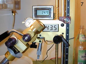
I already had an inexpensive ($8) voltmeter module with an AC adapter and a housing large enough to accomodate the circuitry and a battery for the voltage reference. Figure 7 shows the complete modification with micrometer head and depth-of cut indicator.
This arrangement has increased my enjoyment of faceting - no more accidental angle changes - and I believe it has improved the quality of my work.
Let me know if you find this modification useful.